click for non intrinsically safe version
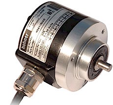
Price 275 USD$ each
Cable Assemblies 2.97 USD$ per m
|____|
Shaft Size
|
|
Resolution - ppr
|
K2 = 6 x 10 mm
|
Exit
|
K4 = 10 x 20 mm
|
A = Axial
|
K5 = 12 x 20 mm
|
R = Radial
|
Connection
IP Rating
1 = 2m cable
HA = IP54
2 = 5m cable
HB = IP65 (standard)
G = 9418 8 pin plug & socket
H = 9512 12 pin plug & socket
5...24 Volt Extended Line Driver is standard, optional Current Sink Open Collector is available

 IECEx
IECEx

Zone 0, Class 1 Div 1