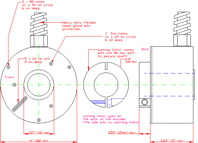
Shaft Size
Connection
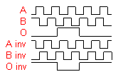
Resolution - ppr
16 = 16 mm
1 = 2m cable
20 = 20 mm
2 = 5m cable
25 = 25 mm
M = 10 cm cable with
30 = 30 mm
a 12 pin plug attached
B1 = 1"
5...24 Volt Extended Line Driver is standard, optional Current Sink Open Collector is available

 IECEx
IECEx

ATEX Certification only is standard