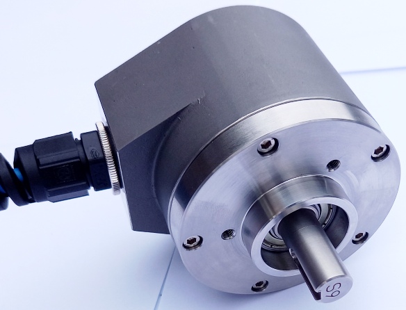
Series IPW incremental shaft encoder up to 12 mm
(non intrinsically safe part number)
|
hohner |
Hohner Automation Ltd. |
| Home | Distributors | Terms | About Us | Accessories | Download 3D AutoCAD |
|
Series IPW incremental shaft encoder up to 12 mm (non intrinsically safe part number)
|
|
|||||||||||||||||||||||||||||||||||||||||||||||||||||||||||||||||||||||||||||||||||||||||||||||||||||||||||||
|
|
|||||||||||||||||||||||||||||||||||||||||||||||||||||||||||||||||||||||||||||||||||||||||||||||||||||||||||||
| X |
Output Signal |
X | Shaft Size | ||||||||||||||||||||||||||||||||||||||||||||||||||||||||||||||||||||||||||||||||||||||||||||||||||||||||||
|
1 = channel A |
J = 10 x 20 mm | ||||||||||||||||||||||||||||||||||||||||||||||||||||||||||||||||||||||||||||||||||||||||||||||||||||||||||||
| 2 = channel A and O | K = 12 x 20 mm | ||||||||||||||||||||||||||||||||||||||||||||||||||||||||||||||||||||||||||||||||||||||||||||||||||||||||||||
| 3 = channel A and B | |||||||||||||||||||||||||||||||||||||||||||||||||||||||||||||||||||||||||||||||||||||||||||||||||||||||||||||
| 4 = channel A, B and O | |||||||||||||||||||||||||||||||||||||||||||||||||||||||||||||||||||||||||||||||||||||||||||||||||||||||||||||
| 5 = channel A and A comp | |||||||||||||||||||||||||||||||||||||||||||||||||||||||||||||||||||||||||||||||||||||||||||||||||||||||||||||
| 6 = channel A & O and A & O comp | |||||||||||||||||||||||||||||||||||||||||||||||||||||||||||||||||||||||||||||||||||||||||||||||||||||||||||||
| 7 = channel A & B and A & B comp | |||||||||||||||||||||||||||||||||||||||||||||||||||||||||||||||||||||||||||||||||||||||||||||||||||||||||||||
| 8 = all six channels | |||||||||||||||||||||||||||||||||||||||||||||||||||||||||||||||||||||||||||||||||||||||||||||||||||||||||||||
| X | Output Circuit | X | Connection | ||||||||||||||||||||||||||||||||||||||||||||||||||||||||||||||||||||||||||||||||||||||||||||||||||||||||||
| 1 = TTL Line Driver | S = 2 m cable, Stainless Steel | ||||||||||||||||||||||||||||||||||||||||||||||||||||||||||||||||||||||||||||||||||||||||||||||||||||||||||||
| 2 = CMOS Line Driver 7-15 Volts | T = 3 m cable, Stainless Steel | ||||||||||||||||||||||||||||||||||||||||||||||||||||||||||||||||||||||||||||||||||||||||||||||||||||||||||||
| 3 = Current Sink 7-30 Volts | U = 4 m cable, Stainless Steel | ||||||||||||||||||||||||||||||||||||||||||||||||||||||||||||||||||||||||||||||||||||||||||||||||||||||||||||
| 4 = Current Source 7-30 Volts | V = 5 m cable, Stainless Steel | ||||||||||||||||||||||||||||||||||||||||||||||||||||||||||||||||||||||||||||||||||||||||||||||||||||||||||||
| 5 = Push Pull 11-30 Volts | W = 8 m cable, Stainless Steel | ||||||||||||||||||||||||||||||||||||||||||||||||||||||||||||||||||||||||||||||||||||||||||||||||||||||||||||
| 6 = Non Existant | Z = 20 m cable, Stainless Steel | ||||||||||||||||||||||||||||||||||||||||||||||||||||||||||||||||||||||||||||||||||||||||||||||||||||||||||||
| 7 = Current Sink / Open Collector | |||||||||||||||||||||||||||||||||||||||||||||||||||||||||||||||||||||||||||||||||||||||||||||||||||||||||||||
| 8 = Current Source / Open Collector | |||||||||||||||||||||||||||||||||||||||||||||||||||||||||||||||||||||||||||||||||||||||||||||||||||||||||||||
| 9 = Extended Line Driver 5-24 Volts | |||||||||||||||||||||||||||||||||||||||||||||||||||||||||||||||||||||||||||||||||||||||||||||||||||||||||||||
| X = 5 Volt Regulator Fitted | |||||||||||||||||||||||||||||||||||||||||||||||||||||||||||||||||||||||||||||||||||||||||||||||||||||||||||||
| T = 8 Volt Regulator Fitted | |||||||||||||||||||||||||||||||||||||||||||||||||||||||||||||||||||||||||||||||||||||||||||||||||||||||||||||
| Y = 12 Volt Regulator Fitted | |||||||||||||||||||||||||||||||||||||||||||||||||||||||||||||||||||||||||||||||||||||||||||||||||||||||||||||
| Z = 15 Volt Regulator Fitted | |||||||||||||||||||||||||||||||||||||||||||||||||||||||||||||||||||||||||||||||||||||||||||||||||||||||||||||
| X | Connection Exit | ||||||||||||||||||||||||||||||||||||||||||||||||||||||||||||||||||||||||||||||||||||||||||||||||||||||||||||
| A = Axial Exit | |||||||||||||||||||||||||||||||||||||||||||||||||||||||||||||||||||||||||||||||||||||||||||||||||||||||||||||
| R = Radial Exit | |||||||||||||||||||||||||||||||||||||||||||||||||||||||||||||||||||||||||||||||||||||||||||||||||||||||||||||
| Technical Data | Connection Options | ||||
| Operating temp: | - 20 ...+ 60 degrees C | Cable | 12 pin | ||
| - 4 ...+ 140 degrees F | PS GND | Black | 1 | ||
| On request: | - 40 degrees | PS 5 ... 24 V | Red | 2 | |
| Max frequency: | 150 kHz | Output A | White | 3 | |
| Current consumption: | 90 mA (max.) | Output B | Blue | 4 | |
| Power supply: | 5 - 24V | Output O | Yellow | 5 | |
| Weight: | 2 kg | Output A inv | Green | 6 | |
| Protection: | IP 66 | Output B inv | Violet | 7 | |
| Housing: | S. Steel | Output O inv | Brown | 8 | |
| Shaft: | Stainless Steel | ||||
| Bearings: | 2 x 6001 - (Z) (RS) | Output | |||
| Torque: | 0.7 oz/in (5 N-cm) | Diagram is shown with clockwise shaft rotation viewed from | |||
| Humidity: | Up to 98% permissible |
shaft end |
|||
| Speed: | 6000 RPM max. |
|
|||
| Shock: | 10g (6msec) | ||||
| Vibration: | 5g (500 Hz) | ||||
| Shaft load: | Radial / Axial 10 N | ||||
| Line driver output max: | 50 mA per channel | ||||
| Max. ppr | 5000 | ||||
| Inertia: | 100 gm-cm2 | ||||
| Mounting Instructions | |
| Hook up the encoder with the connections as described. Make sure power supply meets specifications. Attach encoder to mounting bracket as shown. Attach shaft using a flexible coupling. | |
| Dimensions | |
|
|
|
| Hohner Automation Ltd. | Tel: +44 (0) 1978 363-888 |
| Whitegate Industrial Estate | Fax: +44 (0) 1978 364-586 |
| Wrexham LL13 8UG | E-mail: uksales@hohner.com |
| United Kingdom | Web: www.hohneronline.co.uk |