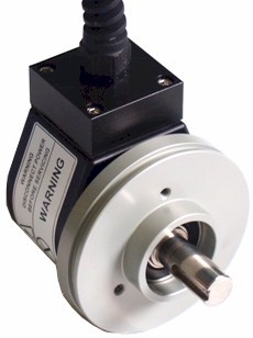
|
|
|
![]()
|
Series W incremental shaft encoder up to 12 mm |
|
|
W | X | X | X | - | 1 | 3 | X | X | - | X | X | X | X | |||||||||||
|
| |
Shaft Size |
| |
| |
|
Resolution - ppr |
||||||||||||||||||||
| | | K2 = 6 x 10 mm | | | Exit | ||||||||||||||||||||||
| | | K4 = 10 x 20 mm | | | A = Axial | ||||||||||||||||||||||
| | | K5 = 12 x 20 mm | | | R = Radial | ||||||||||||||||||||||
| | |
| |
||||||||||||||||||||||||
| Protection | Connection | ||||||||||||||||||||||||
| A = IP54 | 1 = 2m cable | ||||||||||||||||||||||||
| B = IP65 | 2 = 5m cable | ||||||||||||||||||||||||
| G = 9418 8 pin plug & socket | |||||||||||||||||||||||||
| H = 9512 12 plug & socket | |||||||||||||||||||||||||
| 5...24 Volt Extended Line Driver is standard, optional Current Sink Open Collector is available | |||||||||||||||||||||||||
|
|
|||||||||||||||||||||||||
| Technical Data | Connection Options | ||||
| Operating temp: | - 20 ...+ 60 degrees C | Cable | 12 pin | ||
| - 4 ...+ 140 degrees F | PS GND | Black | 1 | ||
| On request: | - 20 ... + 80 degrees C | PS 5 ... 24 V | Red | 2 | |
| Max frequency: | 150 kHz | Output A | White | 3 | |
| Current consumption: | 80 mA (max.) | Output B | Blue | 4 | |
| Power supply: | 5 - 24V | Output O | Yellow | 5 | |
| Weight: | 24 oz (0.8 kg) | Output A inv | Green | 6 | |
| Protection: | IP54 or 65 | Output B inv | Violet | 7 | |
| Housing: | Aluminum | Output O inv | Brown | 8 | |
| Shaft: | Stainless Steel | ||||
| Bearings: | 2 x 6001 - (Z) (RS) | Output | |||
| Torque: | 0.7 oz/in (5 N-cm) | Diagram is shown with clockwise shaft rotation viewed from | |||
| Humidity: | Up to 98% permissible |
shaft end |
|||
| Speed: | 6000 RPM max. |
|
|||
| Shock: | 10g (6msec) | ||||
| Vibration: | 5g (500 Hz) | ||||
| Shaft load: | Radial / Axial 10 N | ||||
| Line driver output max: | 50 mA per channel | ||||
| Max. ppr | 5000 | ||||
| Inertia: | 100 gm-cm2 | ||||
| Certifications | |
| To use the encoder in a hazardous area, a safety barrier has to be used. Our six channel barrier series AB was designed to work with our encoders. Data Sheet | |
| IP 54, 65 | |
| SIRA - N / 520 / 3618 / 4 | |
| IM1 EEx (ia) I | |
| II1G EEx (ia) IIB T4 [Certificate] PDF file | |
| SIRA 02ATEX2317X | |
| UL E216028 | |
| Mounting Instructions | |
| Hook up the encoder with the connections as described. Make sure power supply meets specifications. Attach encoder to mounting bracket as shown. Attach shaft using a flexible coupling. | |
| Dimensions | |
|
|
|
| Hohner Automation Ltd. | Tel: +44 (0) 1978 363-888 |
| Whitegate Industrial Estate | Fax: +44 (0) 1978 364-586 |
| Wrexham LL13 8UG | E-mail: uksales@hohner.com |
| United Kingdom | Web: www.hohneronline.co.uk |