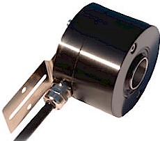
Series 97 incremental hollow shaft encoder up to 20 mm


click for intrinsically safe version

9   7 X X X 6 9 X / X X X X


Shaft Size

|

  |


Resolution - ppr

10 = 10 mm | |
12 = 12 mm | Connection

14 = 14 mm | R = 2 m cable
  16 = 16 mm |   D = 9 pole D
20 = 20 mm | S = 12 pin plug
Protection

3 = IP65, Aluminum
4 = IP65, Stainless Steel
5...24 Volt Extended Line Driver is standard, optional Current Sink Open Collector is available


Select your options below and buy online, easily and securely, with Google Checkout (from £210)


  Shaft           Protection                       Connection                 Resolution      Quantity


Technical Data Connection Options
Operating temp: - 20 ...+   60 degrees C 9 pole D, 12 pin plug Cable
-   4 ...+ 140 degrees F PS GND 1 Black
On request: -20 ... + 80 degrees C PS 5 ... 24 V 2 Red
Max frequency: 100 kHz Output A 3 White
Current consumption: 50 mA (max.) Output B 4 Blue
Power supply: 5 - 24V Output O 5 Yellow
Weight:    16 oz (0.5 kg) Output A inv 6 Green
Protection: IP 65 or 66 Output B inv 7 Violet
Housing: Aluminum or SS Output O inv 8 Brown
Shaft: Stainless Steel
Bearings: Ballraces Output
Torque: 0.4 oz/in (3 N-cm) Diagram is shown with clockwise shaft rotation viewed from 
Humidity: Up to 98% permissible

opposite side to shaft grub screws

Speed:  3000 RPM max.
Shock: 10g (6msec)
Vibration: 5g (500 Hz)
Shaft load: Supports its own weight
Line driver output max: 50 mA per channel
Max. ppr 2500

Mounting Instructions

Mount fixture to the encoder with two M3 screws and two washers. Slide the encoder onto the shaft.  With two 1/4-20 screws, tighten the encoder fixture to the motor-frame or machine.  Keep clearance between the encoder and motor or housing by bending the fixture arms as required.  Tighten the setscrew onto the shaft.  Connect the encoder as per wiring specifications. Make sure power supply is within the proper voltage and current rating.  Encoder can be mounted with the setscrew on the machine side or on the opposite side for either CW or CCW.  See datasheet for CW and CCW directions of the outputs.
 

Technical data for mount:  0.3 mm stainless steel sheet

Dimensions


Hohner Automation Ltd. Tel: +44 (0) 1978 363-888
Whitegate Industrial Estate Fax: +44 (0) 1978 364-586
Wrexham LL13 8UG E-mail: uksales@hohner.com
United Kingdom Web: www.hohneronline.co.uk