Shaft Size
Connection
Resolution - ppr
14 = 14 mm
5...24 Volt Extended Line Driver is standard, optional Current Sink Open Collector is available

 IECEx
IECEx

Zone 0, Class 1 Div 1
|
hohner |
Hohner Automation Ltd. |
| Home | Distributors | Terms | About Us | Accessories | Download 3D AutoCAD |
|
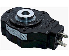
Series 85 incremental encoder up to 20 mm |
|
|
8 | 5 | X | X | - | 1 | 3 | X | R | - | X | X | X | X | |||||||||||
|
Shaft Size |
Connection |
|
Resolution - ppr |
||||||||||||||||||||||
| 10 = 10 mm | 1 = 2m cable | ||||||||||||||||||||||||
| 12 = 12 mm | D = 9 pole D plug & socket | ||||||||||||||||||||||||
|
14 = 14 mm |
|||||||||||||||||||||||||
| 16 = 16 mm | |||||||||||||||||||||||||
| 20 = 20 mm | |||||||||||||||||||||||||
|
5...24 Volt Extended Line Driver is standard, optional Current Sink Open Collector is available
Zone 0, Class 1 Div 1 |
|||||||||||||||||||||||||
| Technical Data | Connection Options | |||||
| Operating temp: | - 20 ...+ 60 degrees C | 9 pole | Cable | |||
| - 4 ...+ 140 degrees F | PS GND | 1 | Black | |||
| Max frequency: | 150 kHz | PS 5 ... 24 V | 2 | Red | ||
| Current consumption: | 50 mA (max.) | Output A | 3 | White | ||
| ( Unloaded ) | Output B | 4 | Blue | |||
| Power supply: | 5 - 24V | Output O | 5 | Yellow | ||
| Weight: | 16 oz (0.45 kg) | Output A inv | 6 | Green | ||
| Protection: | IP 54 | Output B inv | 7 | Violet | ||
| Housing: | Aluminum | Output O inv | 8 | Brown | ||
| Shaft: | Aluminum | |||||
| Bearings: | 2 x 61805 2RZ | Output | ||||
| Torque: | 0.4 oz/in (3 N-cm) | Diagram is shown with clockwise shaft rotation viewed from | ||||
| Humidity: | Up to 98% permissible |
opposite side to shaft grub screws |
||||
| Speed: | 3000 RPM max. |
|
||||
| Shock: | 10g (6msec) | |||||
| Vibration: | 5g (500 Hz) | |||||
| Shaft load: | Radial / axial max 10 lbs | |||||
| Line driver output max: | 50 mA per channel | |||||
| Max. ppr | 1500 | |||||
| Inertia: | 30 gm-cm2 | |||||
| Certifications |
| To use the encoder in a hazardous area, a safety barrier or galvanic isolator has to be used. Our six channel barrier and isolator work with our encoders. Isolator Data Sheet |
| IP 64 S |
| ATEX [Certificate] |
| IECEx [Certificate] |
| CSA [Certificate] |
| GOST-CU [Certificate] |
| Mounting Instructions |
|
Mount fixture to the encoder with three self-tapping no. 8 screws and three no. 8 washers. Slide the encoder onto the shaft. With the setscrew, tighten the hollow shaft onto the shaft. Mount the tether on the machine or motor-frame. The tether can be bent to adapt to any surface. This assembly allows the encoder to float and increases the lifetime of the bearings. Connect the encoder as per wiring specifications. Make sure power supply is within the proper voltage and current rating. Encoder can be mounted with the setscrew on the machine side or on the opposite side for either CW or CCW. See datasheet for CW and CCW directions of the outputs.
Technical data for tether: 0.3 mm stainless steel sheet
|
| Dimensions |
|
|
| Hohner Automation Ltd. | Tel: +44 (0) 1978 363-888 |
| Whitegate Industrial Estate | Fax: +44 (0) 1978 364-586 |
| Wrexham LL13 8UG | E-mail: uksales@hohner.com |
| United Kingdom | Web: www.hohneronline.co.uk |