Shaft Size
Connection
Resolution - ppr
40 = 40 mm

 IECEx
IECEx

Zone 0, Class 1 Div 1
|
hohner |
Hohner Automation Ltd. |
| Home | Distributors | Terms | About Us | Accessories | Download 3D AutoCAD |
|
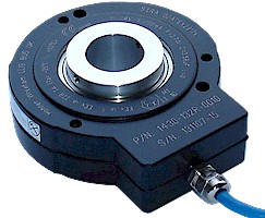
Series 14 NAMUR (DIN 19234) incremental encoder up to 40mm |
|
|
1 | 4 | X | X | - | 0 | 2 | X | R | - | X | X | X | X | |||||||||||
|
Shaft Size |
Connection |
|
Resolution - ppr |
||||||||||||||||||||||
| 25 = 25 mm | 1 = 2m cable attached to 4 pin | ||||||||||||||||||||||||
| 30 = 30 mm | F = 4 pin plug | ||||||||||||||||||||||||
|
40 = 40 mm |
|||||||||||||||||||||||||
| B4 = 1 - 1/4" | |||||||||||||||||||||||||
|
Zone 0, Class 1 Div 1 |
|||||||||||||||||||||||||
| Technical Data | Connection Options | |||||
| Operating temp: | - 20 ...+ 60 degrees C | 4 pin plug | Cable | |||
| - 4 ...+ 140 degrees F | + Loop A | 1 | Red | |||
| Power supply: | 24V | - Loop A | 2 | Black | ||
| Weight: | 39 oz (1.1 kg) | + Loop B | 3 | White | ||
| Protection: | IP 64S, NEMA 3 | - Loop B | scn | Green | ||
| Housing: | Die Cast Zinc Alloy |
|
||||
| Shaft: | Aluminum or SS | |||||
| Bearings: | 2 x 6810 ZZ | |||||
| Torque: | 0.4 oz/in (3 N-cm) | |||||
| Humidity: | Up to 98% permissible |
Output |
||||
| Speed: | 2000 RPM max. | B is phased 90 degrees in front of A in cw direction | ||||
| Shock: | 10g (6msec) |
 |
||||
| Vibration: | 5g (500 Hz) | |||||
| Shaft load: | Radial / axial max 10 lbs | |||||
| Inertia: | 30 gm-cm2 | |||||
| Max. ppr | 512 ppr | |||||
| Speed: |
Limited by frequency response of barrier: Slower for higher resolution. Typical is about 2000rpm for 100ppr |
|||||
| Certifications |
| Best suited to work with the following isolators: P+F KFD2 SOT2 EX2 |
| IP 64S |
| ATEX [Certificate] |
| IECEx [Certificate] |
| CSA [Certificate] |
| GOST-CU [Certificate] |
|
|
| Mounting Instructions |
|
Mount fixture to the
machine with three screws and three washers, M6 or 1/4". Slide the encoder
onto the shaft. With the setscrews, tighten the hollow shaft encoder onto
the shaft with a minimum clearance of 1/16" between fixture and encoder.
This assembly allows the shaft to float and increases the lifetime of the
bearings. Connect the encoder as per wiring specifications. Make sure
power supply is within the proper voltage and current rating. Encoder can
be mounted with the setscrew on the machine side or on the opposite side for
either CW or CCW. See datasheet for CW and CCW directions of the outputs.
Technical data for mount: 1/8" stainless steel wire
|
| Dimensions |
|
|
| Hohner Automation Ltd. | Tel: +44 (0) 1978 363-888 |
| Whitegate Industrial Estate | Fax: +44 (0) 1978 364-586 |
| Wrexham LL13 8UG | E-mail: uksales@hohner.com |
| United Kingdom | Web: www.hohneronline.co.uk |