Shaft Size
Connection
Resolution - ppr
12 = 12 mm
86 = 35 m cable
25 = 25 mm

|
hohner |
Hohner Automation Ltd. |
| Home | Distributors | Terms | About Us | Accessories | Download 3D AutoCAD |
|
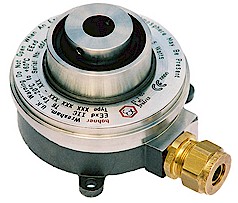
Series 12 flame proof incremental hollow shaft encoder |
|
|
1 | 2 | X | X | - | 0 | 1 | X | X | - | X | X | X | X | |||||||||||
|
Shaft Size |
Connection |
|
Resolution - ppr |
||||||||||||||||||||||
| 03 = 1 / 2 " | 03 = 2 m cable | ||||||||||||||||||||||||
| 05 = 5 / 8 " | 83 = 10 m cable | ||||||||||||||||||||||||
|
12 = 12 mm |
84 = 20 m cable | ||||||||||||||||||||||||
| 14 = 14 mm | 85 = 25 m cable | ||||||||||||||||||||||||
| 16 = 16 mm |
86 = 35 m cable |
||||||||||||||||||||||||
| 20 = 20 mm | |||||||||||||||||||||||||
|
25 = 25 mm |
|||||||||||||||||||||||||
| 5...24 Volt Extended Line Driver is standard, optional Current Sink Open Collector is available | |||||||||||||||||||||||||
|
|
|||||||||||||||||||||||||
| Technical Data | Connection Options | |||
| Operating temp: | - 20 ...+ 60 degrees C | Cable | ||
| - 4 ...+ 140 degrees F | PS GND | Black | ||
| On request: | No option. | PS 5 ... 24 V | Red | |
| Max frequency: | 50 kHz | Output A | White | |
| Current consumption: | 50 mA (max.) | Output B | Blue | |
| Power supply: | 5 - 24V | Output O | Yellow | |
| Weight: | 44 oz (1.25 kg) | Output A inv | Green | |
| Protection: | IP 66 M | Output B inv | Violet | |
| Housing: | Stainless Steel | Output O inv | Brown | |
| Shaft: | Stainless Steel | |||
| Bearings: | 3 x 6907 ZZ C2 | Output | ||
| Torque: | 1.2 oz/in (9 N-cm) | Diagram is shown with counter clockwise shaft rotation | ||
| Humidity: | Up to 98% permissible |
viewed from opposite side to shaft grub screws |
||
| Speed: | 1500 RPM max. |
 |
||
| Shock: | 10g (6msec) | |||
| Vibration: | 5g (500 Hz) | |||
| Shaft load: | Supports its own weight | |||
| Line driver output max: | 50 mA per channel | |||
| Max. ppr | 1500 | |||
| Certifications |
| Does not require a barrier for use in hazardous areas, it is Flameproof, making the barrier redundant. |
| IP 66M |
| Mounting Instructions |
| Mount fixture to the
machine with three screws and three washers, M6 or 1/4". Slide the encoder
onto the shaft. With the setscrews, tighten the hollow shaft encoder onto
the shaft with a minimum clearance of 1/16" between fixture and encoder.
This assembly allows the shaft to float and increases the lifetime of the
bearings. Connect the encoder as per wiring specifications. Make sure
power supply is within the proper voltage and current rating. Encoder can
be mounted with the setscrew on the machine side or on the opposite side for
either CW or CCW. See datasheet for CW and CCW directions of the outputs.
Technical data for mount: 1/8" stainless steel wire
|
| Dimensions |
|
|
| Hohner Automation Ltd. | Tel: +44 (0) 1978 363-888 |
| Whitegate Industrial Estate | Fax: +44 (0) 1978 364-586 |
| Wrexham LL13 8UG | E-mail: uksales@hohner.com |
| United Kingdom | Web: www.hohneronline.co.uk |